[cs_content][cs_section parallax=”false” separator_top_type=”none” separator_top_height=”50px” separator_top_angle_point=”50″ separator_bottom_type=”none” separator_bottom_height=”50px” separator_bottom_angle_point=”50″ style=”margin: 0px;padding: 10px 0px;”][cs_row inner_container=”true” marginless_columns=”false” style=”margin: 0px auto;padding: 0px;”][cs_column fade=”true” fade_animation=”in” fade_animation_offset=”45px” fade_duration=”750″ type=”1/2″ class=”cs-ta-center” style=”padding: 0px;”][x_custom_headline level=”h1″ looks_like=”h3″ accent=”true” class=”cs-ta-center”]Testex Tape; Press-O-Film Replica Tape[/x_custom_headline][cs_text class=”cs-ta-left”]
Testex Press-O-Film replica tape consists of a layer of crushable plastic micro-foam coated onto polyester film of highly uniform thickness.
Why determination of profile is important:
Industrial steel in bridges, ships, rail cars, etc., is almost always painted or otherwise coated to prevent corrosion. Before they can be painted, these metal surfaces must be cleaned and roughened to insure that the paint adheres. This is usually done by grit or shot blasting the surface. If the resulting surface is too smooth, the paint or coating will not stick. If the surface is too rough, the peaks poke through the coating and rusting occurs.
How replica tape allows field (gage) measurement of profile:
When compressed, by “burnishing,” against a surface, the foam collapses to about 25% of its pre-collapse thickness. After compression, the foam acquires an impression of the surface against which it is burnished. The highest peaks on the original surface displace the fully compressed foam and come to rest against the polyester backing. The deepest valleys on the original create the highest peaks in the replica. Consequently, the thickness of the compressed tape equals the average maximum peak-to-valley profile plus the thickness of the incompressible polyester substrate. A spring-loaded micrometer gage is used to measure the thickness of the replica.
Characteristics of the spring micrometer gage:
All characterization of replica tape profile measurements has been performed with a gage having a measurement accuracy of 0.2 mil (5 microns), closing force of 3 ounces (1.1 N) and at least one anvil having a circular diameter of 0.25 inch (6.3 mm). Suitable inch and metric unit gages are available from Testex and other companies but great care should be taken to assure that they are specifically designed to be used with replica tape.
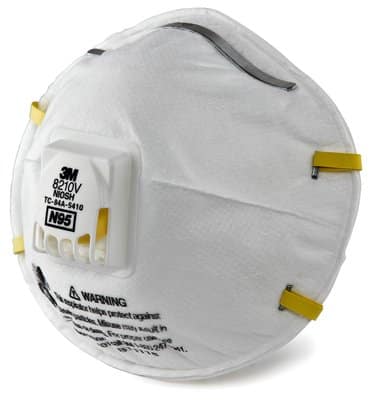
Using the proper gauge is essential to obtaining correct profiles. Please refer to the Mitutoyo Micrometer.
[/cs_text][/cs_column][cs_column fade=”false” fade_animation=”in” fade_animation_offset=”45px” fade_duration=”750″ type=”1/2″ class=”cs-ta-center” style=”padding: 0px;”][x_image type=”none” src=”https://bwdist.com/wp-content/uploads/2017/09/Testex-Tape.jpg” alt=”Testex Tape” link=”false” href=”#” title=”” target=”” info=”none” info_place=”top” info_trigger=”hover” info_content=””][/cs_column][/cs_row][/cs_section][cs_section parallax=”false” separator_top_type=”none” separator_top_height=”50px” separator_top_angle_point=”50″ separator_bottom_type=”none” separator_bottom_height=”50px” separator_bottom_angle_point=”50″ style=”margin: 0px;padding: 45px 0px;”][cs_row inner_container=”true” marginless_columns=”false” style=”margin: 0px auto;padding: 0px;”][cs_column fade=”false” fade_animation=”in” fade_animation_offset=”45px” fade_duration=”750″ type=”1/1″ style=”padding: 0px;”][cs_text class=”cs-ta-center” style=”font-size:16px;”]Click below for the Individual Data Sheet[/cs_text][x_button size=”global” block=”true” circle=”false” icon_only=”false” href=”” title=”” target=”blank” info=”popover” info_place=”top” info_trigger=”hover” info_content=”Click to Download or View Data Sheet”][x_icon type=”download” class=”mvn mln mrs”]Data Sheet Unavailable[/x_button][/cs_column][cs_column fade=”false” fade_animation=”in” fade_animation_offset=”45px” fade_duration=”750″ type=”1/1″ style=”padding-top: 20px;”][x_prompt type=”left” title=”Need Help?” message=”<strong>Questions?</strong> Call us for technical support, product information or help with any questions.” button_text=”480.924.8883″ button_icon=”phone” circle=”false” href=”tel:+14809248883″ href_title=”Call B&W Distributors” target=””][/cs_column][/cs_row][/cs_section][cs_section parallax=”false” separator_top_type=”none” separator_top_height=”50px” separator_top_angle_point=”50″ separator_bottom_type=”none” separator_bottom_height=”50px” separator_bottom_angle_point=”50″ style=”margin: 0px;padding: 45px 0px;”][cs_row inner_container=”true” marginless_columns=”false” style=”margin: 0px auto;padding: 0px;”][cs_column fade=”false” fade_animation=”in” fade_animation_offset=”45px” fade_duration=”750″ type=”1/1″ style=”padding: 0px;”][x_tab_nav type=”three-up” float=”top”][x_tab_nav_item title=”How Replica Tape Works” active=”false”][x_tab_nav_item title=”Press-O-Film HT Instructions” active=”true”][x_tab_nav_item title=”Press-O-Film X-Coarse Plus Grade” active=”false”][/x_tab_nav][x_tabs][x_tab active=”false”]
How Replica Tape Works

- Replica tape consists of a layer of compressible foam affixed to an incompressible polyester substrate.
- When pressed against a roughened (steel) surface, the foam collapses…
- Acquiring an impression of the surface.
- Placing the compressed tape between the anvils of a micrometric thickness gage, and subtracting the contribution of the incompressible substrate (50 micrometers or 0.002 inches), gives a measure of the surface profile.
[/x_tab][x_tab active=”true”]
DETAILED STEP-BY-STEP INSTRUCTIONS FOR USING PRESS-O-FILM WITH A “TESTEX DIAL THICKNESS MICROMETER GAGE”:
Note: The graphic on each piece of tape will help you remember the new (Step 9) averaging procedure.
Step 1: Locate a representative site for measurement.
Step 2: Select an appropriate grade of Press-O-Film replica tape based on your target profile:
For 0.8 to 2.5 mils (20 to 64 um) => “Coarse” grade
For 1.5 to 4.5 mils (38 to 115 um) => “X-Coarse” grade
The primary range for measurement with replica tape is 0.8 to 4.5 mils (20 to 115 um).
Use of Coarse Minus grade (<0.8 mil or <20 um) or X-Coarse Plus grade tape (>4.5 mil or >115 um) should be restricted to checking measurements at the lower or upper ends of the primary range. Further information (pdf format) on X-Coarse Plus grade tape is available here.
Step 3: Prepare the snap gage: clean anvils, adjust zero point to read minus 2.0 mils, the thickness of the incompressible substrate. On a conventional Testex thickness gage a setting of minus 2.0 mils is equivalent to a setting of (plus) 8.0 mils. (Pre-setting the gage in this way subtracts the thickness of the incompressible plastic substrate automatically from all readings.)
Step 4: Pull a single piece of adhesive-backed tape free of its release paper. The Press-O-Film replica material is the 0.4 inch (1.0 cm) square white plastic film at the center of the adhesive-backed paper. A “bulls eye” circle of paper should remain behind on the release paper (i.e., it is not used in the measurement.)
Step 5: A pre-check of film thickness is good practice. Uncompressed X-Coarse grade has a foam thickness of 5.5 mils ( 140 μm ) ± 0.5 mils ( 12 μm ).
Step 6: Apply film to blasted surface. Press adhesive-backed paper to hold it firmly in place.
Step 7: Firmly compress replica film with the smoothest surface on the round-end rubbing tool provided, applying sufficient pressure to produce a replica with a uniform pebblegrain appearance. (In a pinch, the rounded edge of the tape dispenser is also an acceptable tool.) Use either a circular, or x-y rubbing motion. Fully compress all parts of the film but be careful not to slide the film with respect to the blasted surface by bumping edges of the circular paper cutout. In general, too much compression is safer than too little.
Step 8: Remove replica and place between anvils of micrometer gage, making sure replica is centered between anvils. Gage reading is a measure of average maximum peak-to-valley height of the blasted surface (when snap gage is adjusted as in step 3). If differing numerical values are obtained for the same site, the lowest value will tend to occur where the replica foam has been most completely compressed and therefore be the most reliable. Double check using a comparator.
Step 9: If a measurement with either Coarse or X-Coarse grade is in the 1.5 to 2.5 mil (38 to 64 μm) window (inclusive), take a 2nd reading with the OTHER grade. If both readings are in the 1.5 to 2.5 mil (38 to 64 μm) range, record the average as the observed profile.
Readings made with either grade that are outside this range – i.e., between 0.8 and 1.4 mils (20 to 37 μm) or between 2.6 and 4.5 mils (65 and 115 μm) – should be used as is, i.e. without averaging. Note: The graphic on each piece of tape will help you remember this new averaging procedure.
Note 1: Rolls of old formulation (non-HT) Press-O-Film can be safely used with these new instructions.
Note 2: If user circumstances warrant, the new (HT) tape can continue to be used with the old (non-averaging) instructions.
Note 3: “Average” = add the Coarse reading to the X-Coarse reading and divide by 2.
Note 4: Measurements made using the new POF-HT averaging procedure should be marked “HT”. If measurements are made without averaging, they should be marked “non-HT”.
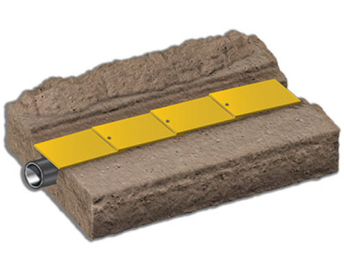
Tape Range Illustration

[/x_tab][x_tab active=”false”]
Information on Press-O-Film X-Coarse Plus Grade
Testex recommends that its X-Coarse Plus film be used only to check profiles determined to be at, or near, the upper limit of its regular X-Coarse tape (range: 1.5 – 4.5 mils, i.e. 40 – 115 um) and that X Coarse Plus measurements be considered valid only to a maximum measured value of 5.0 mils (127 um).
Good practice suggests that measurements made with any grade be regarded with suspicion if those measurements are at, or near, either end of a given grade’s quoted range. For regular X-Coarse grade, the upper end would include any measurements approaching 4.5 mils (115 um). Because no higher grade is available for checking a given X Coarse Plus measurement, we have set 5.0 mils (127 um) as a safe upper limit for a successful measurement with this grade. (Similarly, Coarse Minus grade, used to check measurements at the low end of our Coarse grade’s 0.8 to 2.0 mil, i.e. 12 to 26 um, range, has an arbitrarily-set lower limit.) Procedures for use of X-Coarse Plus grade tape are similar to those applicable to regular X-Coarse grade except for the need to apply greater pressure to fully collapse the tape’s plastic microfoam.
Note: While good practice suggests that an upper limit of 5.0 mils (127 um) be observed, Testex in fact believes its X-Coarse Plus grade to return reliable measurements of profile up to at least 5.8 mils (147 um), implying a range of 4.6 – 5.8 mils (116 – 147 um).[/x_tab][/x_tabs][/cs_column][/cs_row][/cs_section][/cs_content]

